Series And Parallel Batteries Explained
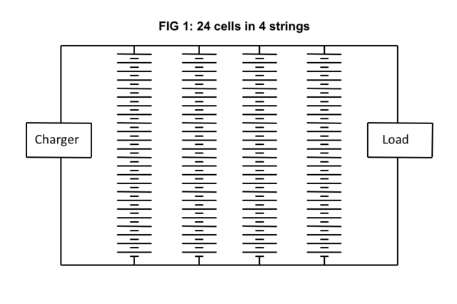
Generally we talk about series connected cells or monoblocs and single or parallel connected strings. For example, a modern telecommunication battery system may have 24 lead-acid cells connected in series and 4 strings connected in parallel. This configuration is illustrated in Fig 1 below.
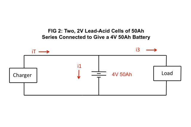
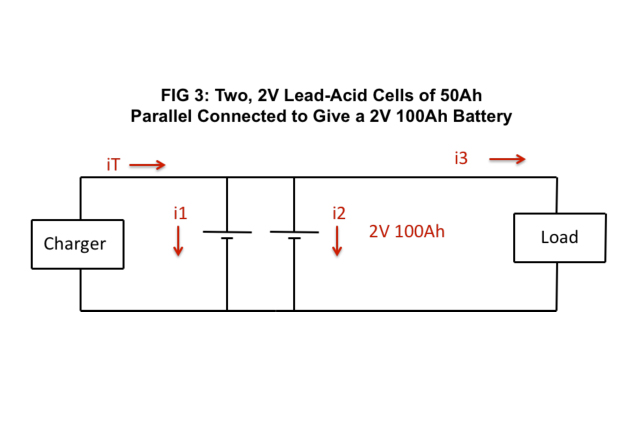
When cells or monoblocs are connected in series the voltage of the system is increased. For example, 2 x 2V lead-acid cells of 50Ah each connected in series would be a battery having a nominal voltage of 4V and a capacity of 50Ah. See FIG 2 below. The same 2 x 2V lead-acid cells of 50Ah each connected in parallel would give a total voltage of 2V and a capacity of 100Ah. See FIG 3 below.
By changing the configuration we can increase the voltage or capacity of a battery system with almost limitless possibilities. However, battery voltages over 1000V are likely to give insulating problems and in practical terms the highest voltage seen in normal commercial use is about 750V. Looking at the capacity, in theory there is no limit to the capacity that can be achieved. There are many examples of parallel connected batteries with a capacity of over 5000Ah.
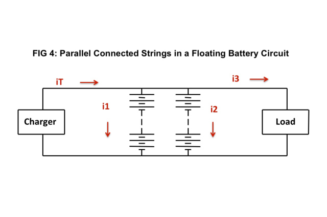
During charging, for the configuration shown in FIG 4 above, the sum of the currents i1, i2 and i3 would total iT. In an ideal situation we would like the charging currents i1 and i2 to be the same. However, in practice we will always find a difference in the charging currents because cells are never identical in a float charge battery system. As the strings become more charged, the current will reduce to a very low value and the effects of voltage drop will be insignificant. Even in fully charged systems a small difference in charging current may be seen. This will be very small because the charging current will be in the order of mA for most battery systems and accurate measurements are difficult to obtain without special equipment. During discharging, we cannot expect the current from string 1 to be identical to string 2. A good guide to a healthy battery system would show the discharge currents in string 1 and 2 to be within 5% of each other and 10% is considered to be the normal limit of variability. Anything more than 10% should be investigated. In an ideal battery system, the cable lengths from the charger to the strings and from the strings to the load should be the same length and the same cross sectional area. This is represented in FIG 5 below. In this way, the volt drop will be very similar and better balancing of the system will be achieved. In practical terms this is not as important as may first be envisaged. During a discharge it is normal that the string currents will be different. At the commencement of the discharge string 1 may have a larger current than string 2 but as the discharge progresses, it is likely that the situation will reverse. In another application, one string may deliver more current than another throughout the discharge. Unless the difference at any time is more than the 10% guideline no corrective action would normally be required.
A further paper titled “Parallel String Batteries in High Voltage Applications” will be published within the near future.