How To Make A VRLA Battery.
INTRODUCTION
This article discusses the manufacturing principals and processes in the manufacture of VRLA batteries. The article discusses the manufacturing processes and how deviations from the ideal can seriously affect the finished product.
The article assumes the reader has a reasonable knowledge of the construction of both AGM and GEL types. The process described here is very much simplified but will give the reader an understanding of the processes involved in manufacturing VRLA batteries.
It has been said that it is very easy to manufacture a bad VRLA battery and quite difficult to manufacture a good performing product having a durable long life. It is the writer’s belief that this is true.
The following notes will help those not familiar with the manufacturing process to understand this article.
a) Lead (Pb): the main ingredient of the negative plate. b) Lead dioxide (PbO2): the main ingredient of the positive plate. c) Dilute sulphuric acid (H2SO4): the third component to make the battery work. d) Lead grids: the essential component which the positive or negative active materials are applied. The grids are the main current carrying component responsible for delivering power from the active materials to the terminals. Lead as Pb active material is a reasonable conductor of power but lead dioxide as PbO2 is a poor conductor and good grid design is essential. e) Plate lug: the upper most part of the grid which is “welded” to the group bar. In battery language, the welding process is called “burning”. f) Plate wires: the vertical and horizontal wires of the plate grid. g) Group burning process: this is the term used in the process where the plates are welded to the group bar or where the group bar is welded to the pillars. h) Flag: the section of the group bar which protrudes above the plate group which is used for the inter cell weld.
THE ACTIVE MATERIAL
All lead acid batteries have three active ingredients; lead (Pb), lead dioxide (PbO2) and dilute sulphuric acid (H2SO4). The principals have been discussed in a previous article titled “HOW DOES A LEAD-ACID BATTERY WORK”.
In addition to the active materials, pure lead or lead alloy grids are required to “hold” the lead and lead dioxide. Separators are required to keep the plates apart and AGM batteries have an absorbent separator to hold acid whilst GEL batteries have special jellified electrolyte.
It is easy to say the active materials are lead (Pb), lead dioxide (PbO2) and dilute sulphuric acid (H2SO4), but, the purity of these materials is critical to performance and life of the finished product. Impurities in the dilute sulphuric acid can affect the initial performance or the life of the product, in some cases resulting in unexpected catastrophic failure. At first sight the purity of the lead used in battery manufacture seems to be fantastic with values of 99.97% pure being quoted. However, 99.99% pure lead is not only superior but desirable... A purity of 99.97% and even lower may be used but the impurities such as iron, manganese, copper and other harmful elements must be closely controlled. Interestingly, it has been proven that trace elements of gold in the lead will enhance both performance and life. Unfortunately, most of the gold today is extracted from lead before the battery manufacturer takes receipt.
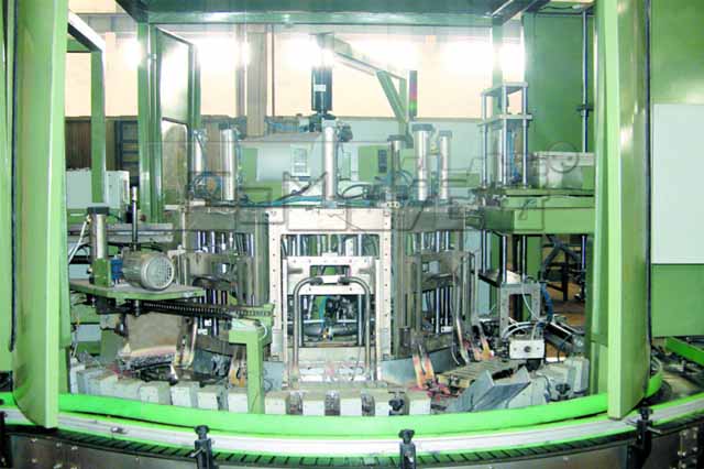
In principal the manufacture of the lead oxide which then becomes lead for the negative plates and lead dioxide for the positive plates should be a simple process. However, the process has to be controlled finitely. Several methods are used to manufacture lead oxide but the most popular are the Barton Pot and Ball Mill. In both, lead oxide is produced in a vessel where fine particles carried away by “extraction” fans are then used to produce the active material. The particle size is very small but the superficial volume is high making the particles act more like dust than lead.
Ball Mill Active Material Manufacturing Machine
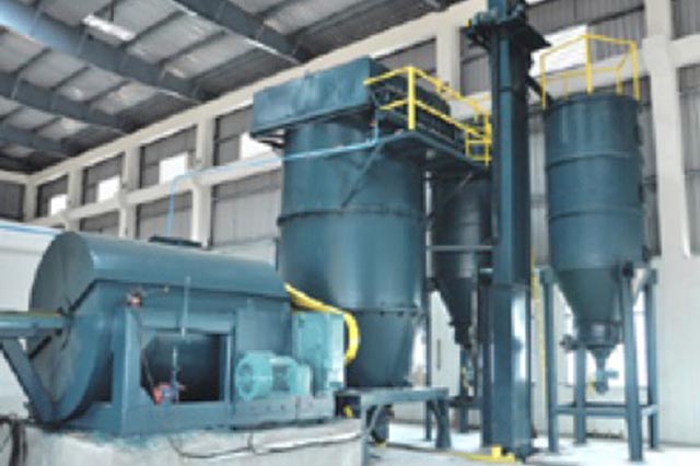
The particles are critically controlled for size, density and “free lead”. Variations in the oxide characteristics will affect the battery performance and life. For example, high “free lead” content will reduce the overall efficiency but can improve the overall life of the product. The finished product characteristics can be “manipulated” by varying the lead oxide characteristics within the Barton Pot or Ball Mill manufacturing process.
The next stage of manufacture involves mixing the lead oxide powder with acid, water, and proprietary additives to produce a paste have a consistency similar to thick toothpaste. This is then pasted onto the lead grids. For VRLA GEL cells using Tubular Plates, the process is quite different and the active material is “inserted” into the tubes as slurry or a dry powder.
Tubular plate cells and increasingly pasted plate types have a rather special lead compound added; triplumbic tetroxide (Pb3O4). This material enhances the plate formation acting as a catalyst to produce a more even and consistent active material in the finished product. It is normally produced by a specialist manufacturing plant rather than the battery manufacturer. Relatively speaking it is several times more expensive to produce when compared with lead oxide (PbO2).
It is normal to add a colour element to differentiate between positive and negative paste. Carbon black is often added which arguably improved conductivity. This is a good identifier.
Areas open to error are:- a) Poor quality control of impurities in the lead, lead alloys and dilute sulphuric acid. b) Poor control of particle size and free lead content. c) Poor control of paste density.
GRID CASTING
Corrosion of the grids is at the front of the battery manufacturers mind and many different alloys and manufacturing methods have been tried to minimise this corrosion. It does not always follow that thick grids will last longer than thin grids. Thick grids will undoubtedly last longer than thin grids, all other aspects remaining the same. Development has taken place and today thin grids with exceptional corrosion resistance are now common place.
The alloys used are normally pure lead, tin, calcium or cadmium. Some exotic alloys are also used but these are very special and not commonly available and in most instances are regarded as “experimental”.
As with the active material, the purity of the lead and alloying element play an important part in achieving the design life. The design of the grids also affects the performance and life of the product. Radial grids are popular with automotive batteries and are increasing in popularity for VRLA industrial products. Inboard lugs, tapered group bars, large inter cell connectors etc all play an important part in the overall design which ultimately will affect the internal resistance and terminal voltage on discharge.
Thin grids have, for many years, been frowned upon but with the availability of very pure lead and by using the correct additives such as tin, superior products have been developed. It is interesting to note that the very first VRLA AGM cells used pure lead grids. The level of tin in the plates varies but typically this is between 2% and 3%. The “hardening agent” such as calcium and cadmium are introduced at much lower levels and it is true to say that the lower the better. Typically 0.05% to 0.10% calcium is added. Some batteries do not contain any “hardening agent” making them delicate to handle in manufacture but resulting in an exceptional product with a very long life.
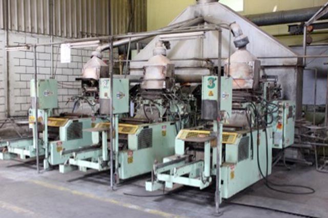
The lead grids are usually manufactured using a gravity casting process. Grid weight is controlled by the operator attending to release agents and mould “maintenance” which is ongoing throughout the casting process. Grids are weighed at regular intervals to ensure compliance with the specification. An under-weight grid will result is a lower performance and a reduced life while a grid heavier than the design specification will cost more in material and profitability will suffer.
Casting Machines
Grids are also manufactured using a rolled and punching method. This latter method results in a very stable grain structure similar to forged steel when compared with case iron. With a more stable grain structure corrosion resistance is enhanced. When a lead tin alloy is used for rolled and punched grids they can be very thin with a finished grid thickness as low as 0.6mm. By using robotic machinery to assemble finished plates into the containers, thinner plates can be accommodated which results in better active material utilisation and superior high rate performance. Unfortunately there is a cost to this process because thin plates are more difficult to handle in a volume production cycle. For many years finished plates were assembled into the containers by hand.
Before pasting the grids with the active material, they are allowed to age harden for several days and sometimes even weeks. The grids become more robust which makes the next stage of pasting easier.
Areas open to error are:-
a) Poor quality control of impurities in the lead. b) Poor control of additive concentrations. c) Poor mixing of the lead and alloying agents. d) Poor control of the casting temperature e) Poor control of the grid thickness.
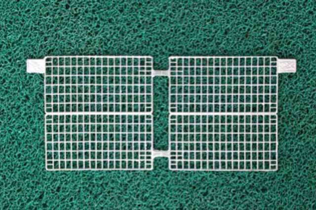
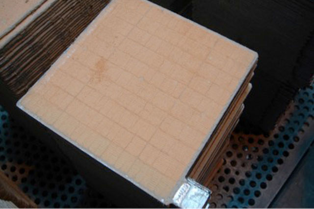
Battery Grid Plates
PASTING
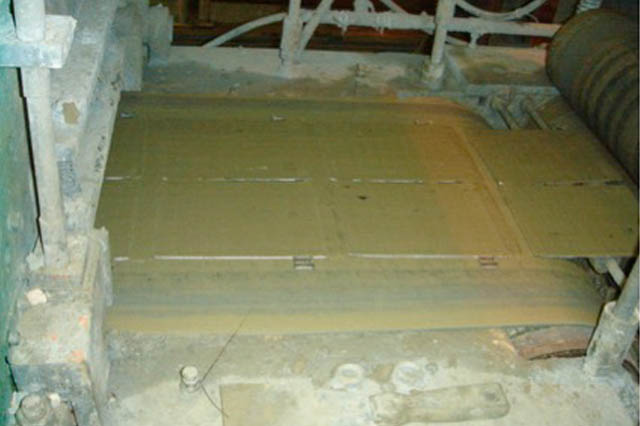
The paste has to be added to the grids and automatic machinery is used for this process. Grids are fed, horizontally, under the head of the pasting machine which normally consists of counter rotating “screws” which force the paste into the grids. The underside of the grid is said to be “flush” while the upper side has a small amount of “over paste”, typically about 0.1mm. At this stage we can call the product “plates”. These plates are fed into a “flash drying oven”. After passing through the flash dryer, plates are sufficiently dry to allow stacking. The flash dryer is a critical area where a good or bad product may be manufactured. If the flash drying temperature is too high a “skin” can form which inhibits plate formation. Both performance and life will be adversely affected. If flash drying is inadequate, plates cannot be stacked separately because they will stick together. With plates not separated correctly the curing process will be affected.
Grids Being Fed In To A Pasting Machine
Plates After Pasting
Before flash drying, some special battery types are returned to the start of the pasting process and turned over before being pasted again. This results in the grid wires being embedded within the plate active material which enhances life. The down side is the additional cost with questionable benefit.
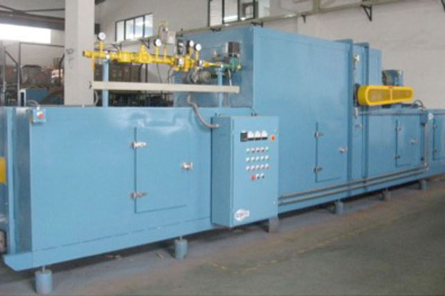
Flash Dryer
For Tubular plates the term pasting is inaccurate because the tubes are filled with positive active material in a power of slurry form. However, this only applies to the positive plate. Negative plates follow the same process for all lead acid battery types.
Areas open to error are:-
a) Inaccurate blending of the dry lead oxide with acid and water. b) Incorrect quantity of additives and / or ineffective mixing. c) Insufficient quantity of active material inserted into the tubes for Tubular plate cells. d) Under pasting resulting in insufficient weight and the consequential loss of performance. e) Missing pellets, i.e. parts of the grid not pasted or sections missing. f) Bent plates as a result of machine settings not correct.
PLATE CURING
After pasting and flash drying the plates are cured. There are several methods for curing plates but the most popular is to use large curing ovens where the oxygen content, temperature and humidity are controlled. It is possible to cure plates without going into a controlled environment but a radically different manufacturing process has to be used later in the manufacturing cycle. The curing process takes time and even when using curing ovens the process takes many hours.
Plates coming out of the ovens should be completely dry.
Areas open to error are:-
a) Poor control of the oven temperature, humidity and oxygen content. b) Curing time too short. c) Stacking in the oven too tight leading to uneven or inadequate drying.
Plates Being Loaded In To Curing Oven
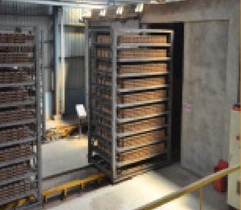
Curing Ovens
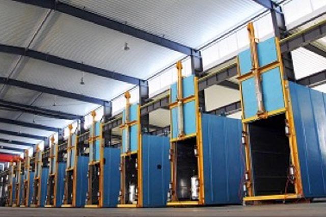
PLATE FINISHING
Before the plates can be assembled into the cells, a finishing process is required to remove paste from the plate lugs, and edges. Loose material must also be removed and this is particularly important for AGM product. A plate having a piece of dried active material on the surface will eventually puncture the separator and a short will be inevitable. Many manufacturers over paste the grids and then plane them down to the correct thickness.
Areas open to error are:-
a) Inadequate cleaning leading to dry paste debris not being removed. b) When plates are planed to the correct thickness, this may not be to the desired design leading to under or over compression in AGM cells.
PLATE STACKING
Plate stacking is where the positive plates, negative plates and separators come together to form a “group” or “stack”. This is more critical in AGM cells compared with GEL types.
Stacking can be either by hand or machine. For AGM cells the separator is more often than not wrapped round one plate or both plates. This may be the positive or negative plate. Occasionally, wrapping is not carried out and a single sheet is inserted between the plates. A very popular process is to wrap both positive and negative plates because two thin layers of separator are better than one thick layer.
For GEL cells a conventional separator is used and the plate stacking process is very much simplified. Double separation is often used which generally is in the form of two different types of separator “bonded” together to form one piece which makes plate stacking very simple. Generally, this process is dome automatically be machine.
Areas open to error are:-
a) Plates can be damaged which may ultimately find their way into finished cells. b) Separator damage may occur.
GROUP BURNING
The term “burning” is used to describe the “welding” process when the plates are connected to the group bar and pillars.
This process involves loading the plate group (see plate stacking above) into a jig ready for group “burning”. The burning process may be by hand or machine. In the case of monoblocs, several cells are normally assembled into a multi cell jig.
Finished Battery Plate Ready To Be Assembled In To The Burning Jig
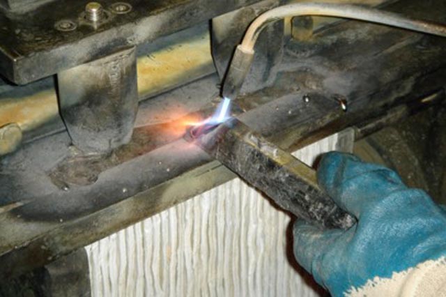
For large cells typically over 500Ah, group burning is generally done by hand involving skilled operators burning (welding) the plate lugs to group bars. The group bar may already be an integral part of the cell pillar or may be formed with molten lead by the operator. The principal is simple to describe but great skill is required to obtain a grain structure which is corrosion resistant. Too much local heat will result is a coarse grain structure at the plate lug / group bar interface which will be liable to rapid corrosion. If too little heat is used, a poor electrical connection will result.
Typical Hand Burning Process
 Smaller capacity cells and monoblocs tend to be assembled using a “cast on process”. This involves loading the plate groups into a jig with the plate lugs uppermost; the jig is then inverted with the plate lugs facing vertically down. The lugs of the complete group or groups are then cleaned and flux is applied... The plate lugs are then dipped into molten lead which effectively welds them together. The molten lead is in a cavity which then forms the group bar and pillar or inter cell “flag”.
Areas open to error are:-
a) Plates not burned (welded) to the group bar adequately. This may lead to local corrosion and premature failure. This may be caused by inadequate lug cleaning, too much or too little flux being applied, plate lugs being misaligned. b) Too much heat applied during the burning process resulting in a coarse grain structure susceptible to corrosion. c) Poor choice of lead alloy leading to early corrosion of the group bar / pillar.
CELL ASSEMBLY
This is the mechanical process of inserting the plate group into the container. It is purely mechanical but can lead to early failure of the product if not controlled.
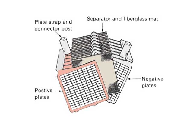
Exploded View Of A Cell Group
VRLA AGM cells have a microfiber separator which relies on being compressed in the finished product. As a plate group it will the larger than the cell container and must be compressed and “shoe horned” into the container. The procedure may involve a machine to ram the group through a tapered “shoe horn” or for small cells a hand insertion method may be used.
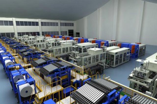
VRLA Battery Assembly Line
VRLA GEL cells are easier to assemble because the group is not a compression fit into the container. Simple machines or a hand insertion method may be used.
Areas open to error are:-
a) Over compression at the “shoe horn” stage leading to fractures in the micro fibre. This may ultimately lead to loss of compression and failure of the product. b) Incorrect alignment of the “shoe horn” to the container leading to snagged plates which can lead to internal shorts.
INTERCELL WELD
For monoblocs, an inert cell connection must be made. Very occasionally this is done externally in a similar way to connecting single cells in series. However, most monoblocs have an inter cell weld. This is normally achieved by an “extrusion fusion” method which, in mechanical terms is a spot weld. The process has to be controlled very closely because the weld is “through” the inter cell wall and it has to be acid tight as well as being electrically correct.
The process involves applying pressure to the group flags which will force lead through the cell wall. With pressure still applied, a high current is applied which melts the lead at the electrodes. With pressure still applied, the current flow is stopped to allow the lead to solidify and finally, the pressure applied by the electrodes is removed.
Areas open to error are:-
a) Poor alignment of the electrodes. b) Inadequate electrode pressure c) Bad current control. d) Worn electrodes
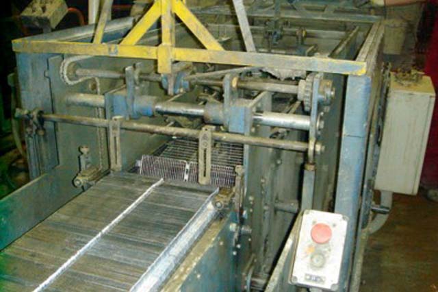
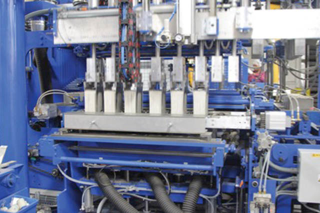
Typical Cast On Strap Machine
Cast On Strap Machine Being Loaded
LID SEALING
Having inserted the plate group into the cell, and completed the inter cell welds for monobloc types, the lid must be fitted. The lids are normally sealed to the container by either; a) heat seal method or b) adhesive bonding. Some small cell lids are ultrasonic sealed but this method is the quite rare for industrial batteries above 25Ah.
As the term implies, heat sealing involves applying heat and bonding the lid to the container. It is normal for a hot plate to heat the mating surfaces of both lid and container and while the mating surfaces are still in a semi-molten state the two components are brought together. The method is well proven and very reliable.
Adhesive bonding is very popular because a “hot plate” does not have to be manufactured for every combination of lid and container. Adhesives normally come in the form of the two-part mixed at the point of application. Large cells and those with low volume production runs are more than often adhesive bonded. Modern adhesives are extremely strong and reliable but some polymers cannot be easily bonded and heat sealing is the only solution.
It is normal to pressure test cells after lid sealing. Often very high critically important product, every cell may be tested using helium which is very searching.
Areas open to error are:-
a) Poor heat bonding caused by inaccurate machine setup. Too hot, to cold, wrong cycle time and misalignment of tooling contribute or cause poor heat bonding. b) Adhesive bonding problems can occur due to inadequate adhesive being applied, or a poor mixing of the two parts.
FORMATION
Some products have plates formed prior to cell assembly in a process known as “tank formation”. The alternative formation process is known as “container formation” where cells are filled with acid and the formation process is carried out.
Arguably, “tank formation” is more reliable because the temperature can be more closely controlled and the acid circulation is achieved. The down side is that the process is considerably more expensive than “container formation”.
Cells going through the “container formation” process must first be filled with acid which normally ends up as the finished cell electrolyte. However, some large GEL cells are formed with a disposable liquid acid which is then dumped before the cell is filled with the finished acid mix. Inn GEL cells the acid mix is formed by adding fine silica, and other proprietary ingredients to dilute sulphuric acid. This produces a milky acid mix which is thixotropic. The mixture is poured into the cells and soon sets into a GEL forming the electrolyte.
The process for VRLA AGM cells following the container formation process, normally involves filling with cold acid typically of about +5C. As soon as the acid reaches the plates which at this stage are in the lead oxide (PbO) form, considerable heat is generated and this must be controlled. Cells or monoblocs are normally formed in water filled baths to control the temperature. Filling the cells is quite complex because the micro-fibre separator does not allow instant filling. Typically, a vacuum will be pulled before acid is allowed to flow into the cell. Most processes involve several pulses of pulling a vacuum and acid flow.
The actual formation process involves putting typically, 7 to 10 times the nominal Ah capacity of the cell into the cells. For example, a nominal 100Ah cell will have 700Ah to 1000Ah input before it may be considered fully formed.
The process normally involves a controlled discharge part way through to check the capacity and “exercise” the active materials.
The formation process is critical the performance and life of the finished product.
Areas open to error are:-
a) Inadequate acid filling. This is more likely to occur on AGM cells and large tubular plate GEL cells. b) Poor mixing of the silica and acid for GEL cells. c) Poor temperature control during the formation process. d) Inadequate capacity input.
PRODUCT FINISHING
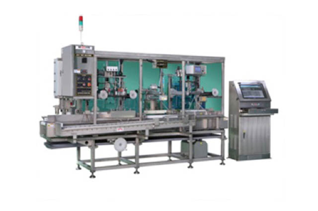
Most products are checked for voltage and some type of conductance, impedance or performance testing is carried out prior to despatch.
This is the “final” QA check that the product normally must pass before packing and shipment.
Areas open to error are:-
a) Inadequate checks allowing defective product through and into the supply chain.
Machine For Final Testing Of Voltage & Impedance
CONCLUSIONS
This document covers the more obvious and more critical processes used to manufacture a VRLA battery.
Because batteries are not regarded as “exciting” and are a “low tech” product, the complexity of manufacture is not interesting to the lay man. This article is written to illustrate that the processes are far from simple and extremely complex.
The article only “skims” over the subject of metals used but these are critical if a high quality; long life product is to be manufactured.