VRLA Battery Charging Methods & Considerations.
This article discusses charging of lead-acid industrial standby batteries on float charge and “off mains” locations. It does not include charging of batteries on full cycling applications such as daily traction duties or similar.
Charging of parallel battery strings, inrush currents, ripple voltage and ripple current are also discussed in outline.
FULL FLOAT CHARGING
The majority of industrial standby batteries are charged using a Full Float Charging system but Pulse Charging is becoming popular particularly for UPS systems. In the main, the chargers are of the thyristor or switch mode type. Both types have some advantages over the other and for a detailed evaluation of each type it is advisable to contact the charger manufacturer direct and discuss the options.
In Full Float Charging it is intended to continuously charge the battery 24 hours a day, 365 days a year and the only exception will be when a mains power failure occurs or during testing and servicing.
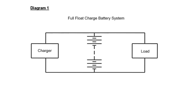
Generally, battery manufacturers prefer this method of charging because it is fully automatic in providing the current that the battery requires, irrespective of the state of charge. The battery and charger are in parallel. This system is a full “no break” system. See the Diagram 1 below.
Diagram 1.
When voltage is applied to the battery terminals, current will flow. It has to be remembered that voltage does not charge the battery; it is the resultant current that will maintain the battery in a constant state of charge or recharge following a discharge. The value of the current going into the battery will depend on its state of charge, battery temperature and type of battery. Typically, but depending on the battery type; the applied voltage will be between 2.23Vpc and 2.28Vpc for a battery temperature of 20oC. Different applied voltages are used for different battery temperatures. The maximum resultant current will depend on the charger current output rating. When the battery is fully charged, the current will be very low and may be as small as 10mA per 100Ah of battery capacity. However, International Standards give guide lines of 1mA per Ah to 8mA per Ah depending on battery type. These values are published as being the typical maximum and have a large “safety margin” in them. Never the less, the current will be very small and in most cases, it cannot be measure without the correct current measuring instruments. A simple “clamp on” ammeter is unlikely to measure the current or the displayed value may be widely inaccurate. It is impossible to accurately measure the current in a fully charged battery with a 200A or even a 20A “clamp on” ammeter when the actual current in a 100Ah battery will normally be in the order of 25mA.
Chargers are normally current rated to supply the full load plus the minimum required for the battery which is typically between 5% and 10% C10 amperes depending on the battery type and manufacturers recommendations. If the system is for a short standby time an interesting scenario may arise. For example, if the load is 250A but is only required for 5 minutes, then the battery capacity will be low and in the order of 75Ah depending on the operating temperature and minimum voltage. If we consider a recharge current of 10% C10A i.e. 7.5A for the battery then the charger will need to have a current rating of about 250A to cater for the standing load of 250A plus 7.5A to recharge the battery, i.e. 257.5A. If a power failure occurs the battery will discharge into the load at the 250A required until the battery is exhausted, or until the mains power is restored, or until the load is disconnected. Either way, the battery will not be fully charged when the charging source is restored. If the load is disconnected from the battery for the recharge, the full charger current capability will be available to recharge the battery.
Under these circumstances the initial recharge current flowing in the battery will be considerable but because the voltage is limited this is not normally an issue. The back EMF of the battery being charged will rise very fast and will meet the float voltage quickly. In some instances, the time to the float voltage may be only a few seconds. However, there is the possibility for this current to flow for many seconds or even longer and there is a danger that any fuses or OCB protection in the battery circuit may be affected. For this reason, battery chargers are often designed in two sections, one for the load and one for battery recharging. Batteries themselves are rarely affected by this high initial recharge current and the effects can largely be ignored for Full Float Charge systems. To avoid any problems with fuses or OCB protection, this is often omitted between the battery and charger.
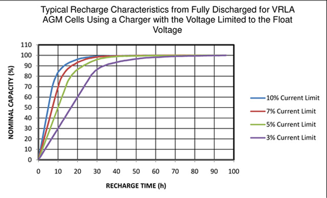
For float recharge systems, the time to fully charged does not change significantly for recharge currents between 3% and 10% and even at higher currents the time to fully charged still remains more or less the same at typically 3 days. However, the time to a state of charge of about 80% or less does change. The value of 80% is typically the state of charge when the float voltage is reached and this is more or less irrespective of the current available to the battery. This is illustrated in Fig 1 below for recharge currents between 3% and 10% C10A. Up to an 80% state of charge the Ah efficiency is close to 100%. Beyond this point, the efficiency gradually falls away until the battery is fully charged when the efficiency can be said to be 0%. Once the battery is fully charged the energy is lost in heat, battery corrosion electrolyte losses etc.
Fig 1.
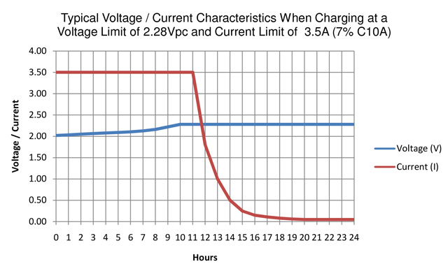
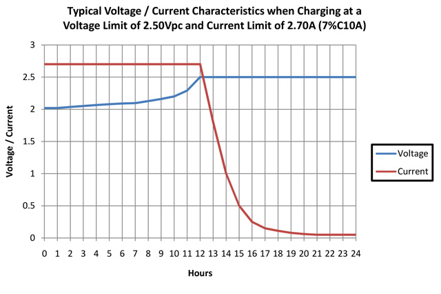
The relationship between recharge current and voltage is illustrated in Fig 2 below.
It can be seen that the charging current falls rapidly once the float voltage is reached and in this case this is after approximately 11 hours of charging. Referring to Fig 1, it can be seen that a charge condition of 80% is achieved after approximately 11 hours when using a current limit of 7% C10A.
Fig 2.
PULSE CHARGING
Pulse Charging can be in several forms but as the term suggests, the charge is delivered in a series of pulses.
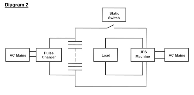
Pulses of charge may be delivered to the battery at time intervals dependant on the charger settings. The interval between charging may be as short as 1 second or many minutes. Some systems charge for 1 second, then rest for 1 second and this is continuous. Where the pulse intervals are short, the control voltage will be close to the normal Full Float charge value. Some systems charge at the Full Float voltage until the current has fallen to a pre-determined level or for a set time at which point the battery is put onto open circuit. Over several hours the voltage will gradually fall and at a pre-determined value charging recommences. Some systems charge a higher voltage such as 2.35Vpc before returning to the normal 2.23Vpc to 2.28Vpc value. For these systems, the battery is not connected directly to the load but only to the charger. A fast acting static switch is employed to reconnect the battery to the load in the event of a mains power failure. This system is illustrated in Diagram 2 below in outline for a UPS system.
Diagram 2.
CONSTANT CURRENT CHARGING
This method of charging is normally reserved for commission charging vented batteries such as Planté, Tubular and Pasted plate types. Constant Current Charging should not be used with VRLA cells without specialist information from the battery manufacturer.
The best way to charge by constant current is to have a charger where both the voltage and current are adjustable. Initially, both voltage and current control should be set to a minimum. The voltage and current should be adjusted slowly until current starts to flow. Typically, once the current has started to flow, the voltage should be adjusted to the maximum available for the charger and the current control adjusted to the correct value. During this process, the actual voltage seen across the battery will not change because the current controller limits the current flowing and hence the voltage across the battery. At this point the current can be adjusted to the required value. Charging will then continue at a constant current and as the battery reaches about 80% charged, the voltage will be seen to increase. However, if the maximum voltage of the charger cannot be adjusted to about 3.00Vpc, then the current may not be constant for the complete charging process. For example, if the maximum voltage of the charger is 2.50Vpc, the current will remain constant until this voltage is reached and then the current will taper off and the voltage will remain steady at 2.50Vpc: this is not constant current charging.
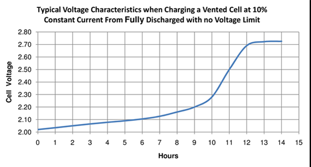
Figure 3 below shows the typical voltage characteristics when charging a vented cell from fully discharged at a constant current of 10%
More information on charging with a voltage limit of 2.50Vpc can be seen below in the section titled Limited Voltage Charging.
Fig 3.
LIMITED VOLTAGE CHARGING
Limited voltage charging is similar to Full Float Charging but instead of using the float voltage which is typically in the order of 2.23Vpc to 2.28Vpc, a higher voltage is used. This type of charging system is often found where the voltage of the charger has an upper limit which is below the natural cell voltage maximum which is in the order of 2.80Vpc to 3.00Vpc. Voltage limits above 2.40Vpc should only be used under guidance from the battery manufacturer.
Limits to the maximum charger voltage are often imposed to protect the load from a voltage that may cause damage. A voltage of 2.40Vpc is often referred to as an equalizing charge. When fully charged, the current flowing in a VRLA cell at 2.40Vpc is typically 8 times that flowing at the float voltage of 2.23Vpc to 2.28Vpc, i.e., about 8mA per Ah. For Vented products such as Planté, Tubular or Pasted Plate, the current will be typically 20mA per Ah.
The higher the voltage limit, the shorter the recharge time will be. However, once the cell voltage reaches the voltage limit of the charger, the current diminishes at a rapid rate. This is illustrated below in Fig 4.
Fig 4
This charging regime is often misinterpreted as constant current because, in some cases the current is seen to be constant for some time before the voltage limit is reached and because it is not a float charge mode. Frequently, chargers have two settings “float” and “equalising”.
The time to fully charged from fully discharged is shorter than using the Full Float method but is considerably longer than using Constant Current. Some manufacturers will not accept this method for commission charging vented products such as Planté, Tubular and Pasted Plate types.
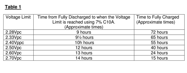
Table 1 below gives an indication of the time taken to reach the voltage limit and the time to fully charged. The current available is taken as 7% C10A.
Table 1
OFF MAINS CHARGING
Off Mains Charging is often used in rural locations where no a.c. mains supply is available. Examples are country houses and telecommunication systems in remote locations. In the vast majority of applications a generator is provided but to avoid having to run this continuously a battery is used. The battery may be charged by a wind generator or solar system, or both, in addition to a generator. In these applications, the battery will at some time need to be brought back to a near fully charged condition if a satisfactory life is to be obtained. Continual undercharging will result is sulphation of the battery plates and premature failure. For systems with wind or solar power, a full recharge may only be required after many months and in some cases this may extend to a full year. In all cases, a full recharge once per year is normally recommended by the battery manufacturer. Typically a constant current recharge is used but a recharge at a value of about 2.50Vpc may prove sufficient.
For county houses the system usually consists of a d.c. generator and battery only. The d.c. power is supplied through an inverter to the normal 240V a.c. house load. To avoid unnecessary noise, the generator may be run through the day and turned off at night. Some systems may run on the battery for several days before recharging is necessary. Again, a full recharge is advisable at least once a year.
To reduce the battery size and if no other charging source is available other than by generator, an automatic system may be used. Country houses often use this system. To obtain a satisfactory life the battery may be charged daily up to a voltage of typically 2.35Vpc to 2.45Vpc and then reduced to a more value typical of a full float system. In this way, the battery will receive a good charge without being overcharged.
It may be argued that a full float system may be more appropriate to avoid overcharging but there is a real risk of undercharging if a value in the order of 2.23Vpc to 2.28Vpc is used. The Full Float Charging is intended for batteries which will only be discharged rarely and typically no more than 4 times a year. The Full Float Charger will not adequately recharge a battery on an Off Mains installation which is subject to regular discharges.
PARALLEL BATTERY STRINGS
Providing all the strings in the battery are in good condition, no issues should be experienced. However, charging of parallel strings can present some interesting characteristics. For example, as on discharge, the recharge current in each string may be marginally different and providing they are within 10% of each other it is reasonable to consider as normal. However, if the currents are more than 10% difference it would be prudent to investigate. The cause may be they are a different state of charge and then the question arises – why? If the battery is new, the differences will stabilize after a good charge.
Occasionally, battery systems are made up on multiple strings but test discharged as individual strings. In these circumstances, it is important to recharge each string independently following a discharge test and before reconnecting to the other string or strings. If this is not carried out and the discharged battery is connected to the fully charged strings, two unwanted characteristics will occur. First, there will be a very large inrush current into the discharged string from the charged string(s). Protection may be affected. Second, considering a two string system, the second string will not be fully charged because of the energy transferred to the first string. Testing of the second string will not be correct because it will not be fully charged unless it is allowed to remain on float charge for several days. The system is further complicated when more than two strings are involved.
INRUSH CURRENTS
The inrush current into a fully discharged battery can be very high and in the order of 3 or 4 times the Ah capacity of the battery. This is not normally a problem because the back EMF of the battery will rise very quickly, within seconds in some cases, to meet the applied charging voltage and the current will rapidly fall away.
Under normal conditions, the charging source will have a current limit and the maximum inrush current will be the maximum of the charging source.
RIPPLE CURRENT AND RIPPLE VOLTAGE
International standards discuss this but in all cases; the manufacturer’s instructions should be followed.
Excessive ripple voltage will cause a higher than desirable ripple current and batteries have been known to fail after a very short time when the charging source has excessive ripple.
Corrosion due to cycling by the ripple or heat will reduce the battery life.
In Planté batteries, cases have been recorded where catastrophic failure has occurred within a few hours. Rapid corrosion of the positive plates takes place which is normally seen as a white deposit in the base of the cells. This is easily identified because the containers are transparent. In VRLA cells with opaque containers, it is not possible to identify the problem until it is too late. VRLA cells are affected very differently to Planté or other vented products. Because the state of charge of the negative plates in a VRLA cell are inevitable in a less than 100% state of charge, it is these where the problem is seen. Corrosion of the negative grid wires takes place and the state of charge is very low. Ripple will cause heating and the life may be reduced without abnormal corrosion characteristics. However, the occurrence of “a.c” corrosion is rare in VRLA cells and the effects are not fully proven.
CONCLUSIONS
At first, the charging of industrial standby batteries seems simple but to obtain a satisfactory life and performance it should not be taken lightly.
The manufacturer’s instructions should be followed without deviation and any suggestion of using an alternative method of charging must be approved by the manufacturer.
Manufacturers are increasingly concerned about the effects of pulse charging which is being promoted as an energy saving feature. However, there is no evidence that pulse charging does save energy and it has been argued that pulsing can cause additional heat within the cells and reduce the life. Long term “field testing” continues.