A Guide To Lead Acid Battery Connectors.
This article discusses the different type of connectors used for batteries in float standby applications. It does not consider traction batteries or those used for cycling applications but some of the practices can be translated to all battery types. The document discusses inter monobloc, inter cell, inter row, inter tier and connectors from the last cell to the transition box, fuse box, or main switch. It does not consider connections from the transition box etc to the load. However, it does make reference to these connections in respect of volt drop.
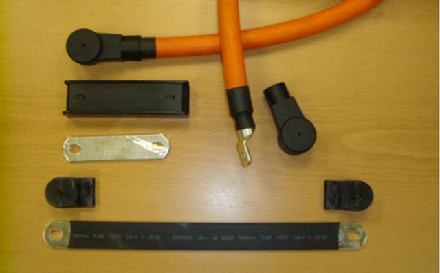
TYPICAL CONNECTORS & COVERS
CONNECTOR INSULATION
Irrespective of the voltage of the battery, all connectors should be insulated. For batteries above 60 cells it is a requirement to insulate the complete battery including the connectors to prevent direct contact. Full details may be found in the latest edition of EN 50272 - Safety Requirements for Secondary Batteries and Battery Installations.
SOLID CONNECTORS
In the most part, inter bloc and inter cell connectors are a solid copper connector usually tinned or similar and very occasionally lead plated. These are generally insulated by a clip on plastic cover to prevent direct contact. Some connectors have a “shrink” heated sleeve and occasionally a cover is provided that will completely cover the top of the bloc or cell. Solid connectors have advantages over other types because no end lug is required and they are bolted direct to the monobloc or cell terminal.
FLEXIBLE CABLE CONNECTORS
These require some special thought because of the complexity they offer.
The connector should be as short as practically possible to keep volt drop to a minimum, the cable lugs will require an insulating cover and the method of attaching the cable lug to the cable must be controlled.
Different types of cable may be used from multi strand flexible “welding cable” type to large diameter strands making the cable very stiff and more like a solid copper connector. In all cases, the correct crimping machine and die must be used to connect the lug to the cable. A different die will be require for a multi strand welding cable of 70mm2 using strands of 0.3mm diameter when compared with a 70mm2 having strands of 0.7mm diameter. During manufacture, a quality plan needs to be implemented to ensure the correct crimp is achieved. Poor crimping may lead to a high resistance joint, excessive voltage drop, overheating and the possibility of a fire.
BRAIDED CONNECTORS
Some battery manufacturer’s offer braided connectors. These have advantages over cable and solid connectors because they are more flexible and offer a tolerance in three dimensions. As with solid connectors they may be insulated with a “heat shrink” cover or complete monobloc or cell cover. Because braided connectors are flexible in three dimensions they are often used where a seismic resistance is required.
FLAME RETARDANT
The flame retardant properties of connectors must be considered. If the battery has to comply with the appropriate EN standard for flame retardant levels, this must include the connectors. Both cable and braised connectors and end lug covers are available with different flame retardant levels. The flammability of containers, lids and covers are discussed in the appropriate EN where the manufacturer must state V0, V1 or V2 and this requirement also applies to the connectors.
CURRENT RATINGS
The current rating of connectors does not follow conventional standards for current carrying capabilities. The connectors are an integral part of the battery and manufacturer’s data considers the standard supplied connector volt drop and heat gain. In this respect, if an alternative connector is used there may be consequences in respect of voltage drop and temperature. However, in the majority of cases the connector cross sectional area (CSA) for battery connectors will be lower than that recommended for normal continuous rated cables. This is because the current will not be continuous but will have a finite run time depending on the battery size and load.
An example of the typical connector cross sectional area CSA with the typical tri rated cable current ratings is given below.
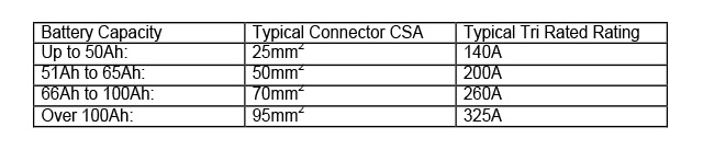
The CSA of the inter connectors used by most battery manufacturers do not follow BS or International recommendations / regulations for cables and conductors. The Standards will normally consider continuous running and for a battery this is not the case. The higher the current being drawn from the battery and the shorter the discharge time will be For example, a battery on discharge at the 1 minute rate may have a current of 500A but the 1 minute duration is insufficient to cause any heat problems providing the manufacturers connector is used. However, in many cases, the connector size chosen by the manufacturer is larger in CSA that most Standards recommend. This is to keep the voltage drop within tight limitations specifically for high currents and ensure sufficient contact area is available between the connector and cell terminal pillar. In many cases, even for low current applications, the manufacturer’s standard connector should be used. Some manufacturers will stipulate a larger connector for discharge rates shorter than 1 hour or in some cases 15 minutes. It is always recommended to advise the manufacturer of the discharge rates that the battery will be subjected to.
TORQUE VALUES AND CORROSION PROTECTION
It is essential that the correct torque value is used for the connectors. Over tightening can damage the threads or even break the stud for male connector posts. Under tightening will inevitable result in a higher connector to pillar resistance which in the extreme may lead to a fire from overheating. The author has seen many examples where the pillar has melted as the result of poor connections cause by under tightening or cross threaded nuts.
The subject of applying a corrosion inhibiting gel or “grease” to the terminals remains in debate. Whilst it is important to ensure the mating surfaces are clean some argue that a layer of “grease” similar to petroleum jelly is beneficial. There is no hard and fast rule for this and advice should be sought from the battery manufacturer. However, it is the author’s opinion that vented cell connections and connectors should have some protection. Vented cells on boost charge can give off a fine acid mist and unless the connection and connectors are protected, corrosion will follow.
VOLTAGE DROP
Manufacturer’s data will normally consider the use of the standard connector and battery calculations consider the voltage at the last cell terminal; this is usually referred to as “the battery terminals”. From a practical point of view, the length of cable from “the battery terminal” to the load may be considerable. Consideration needs to be applied to ensure the voltage at the equipment does not fall below the minimum required as a result of excessive voltage drop. In many cases, the cable between the battery terminal and load will have a larger CSA than the inter cell or inter bloc connectors.
Battery layouts requiring a large number of flexible connectors may result in a high voltage drop. It may be necessary to increase the battery ampere hour capacity to compensate. Some complicated layouts, particularly those involving battery enclosures, may have a connector length more than 10 times that when using the standard connector. This is often overlooked by the battery enclosure designer.
CONCLUSION BULLET POINTS
• Always use connectors supplied by the battery manufacturer or those approved by them.
• Advise the manufacturer of the duty requirement to ensure the correct connectors are supplied.
• Ensure connectors are correctly fitted and the correct torque is used.
• Where flexible connectors are used ensure the correct cable lug is fitted and crimped using the specified die.
We hope our continued guide to lead acid batteries proves useful, we will continue to add more articles for information and discussion. Should you wish to address a specific subject with us please contact Blue Box Batteries today.